first post here on trim tabs...

Gnarlykaw

New member
Hey all, thanks for pointing me here from FB, and I knew about the chap forum folding up like a card table...
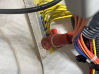
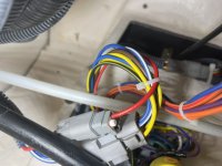
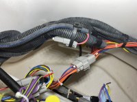
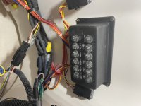
Im in the middle of installing Bennett trim tabs, and were down to wiring. I have worked with fuse blocks that were PCM's on cars, but this breaker box thing is throwing me...
I need a ground, i guess i could run one, but i need a 5A ignition switch feed. in the automotive world, wiring diagrams are available, in boating?? LOL!! fat chance! anybody wanna lead me on this simple task? 2013 246 SSI WT.
Oh, and one more thing, and this one has me worried. i marked the depth of my drill bit for the tab hinge screws, and on one hole, i got a hiss from it when i pulled the drill bit out. NO, I didnt drill through a line, hose, or a tank, but maybe it was a vacuum seal of the hull? All the screw holes got 3m 5200 injected to them, the screws got coated, and i beveled the gelcoat at the holes...
 

Denny

Well-known member
Gold Site Supporter
Did they give you an internal wiring diagram for the unit itself? Using the proper size wire all you need is a ground from anywhere, a positive wire with an inline fuse.
 

dan02gt

New member
So which trim tabs are you trying to install, Bolt electric or hydraulic? I have Bennett Bolts on my 226 SSi and can be of some help. I've also installed the hydraulic ones on a previous boat.

You're fine on the drilling of the holes for the tabs. The area you drilled into is foam filled and should be sealed to keep water out. More than likely there was a little vacuum or pressure on it.
 

dan02gt

New member
They now have foam in transoms?
Not on the center section of the transom where the outdrive is. On outer areas of the Extended V-Plane hull where you mount the tabs the transom is just 1/4" or less of glass and on the backside of that glass is the void that's filled with the floatation foam.
 

Denny

Well-known member
Gold Site Supporter
Ok thanks, is that the design where the tabs mount from the under side?
 

Gnarlykaw

New member
So which trim tabs are you trying to install, Bolt electric or hydraulic? I have Bennett Bolts on my 226 SSi and can be of some help. I've also installed the hydraulic ones on a previous boat.

You're fine on the drilling of the holes for the tabs. The area you drilled into is foam filled and should be sealed to keep water out. More than likely there was a little vacuum or pressure on it.
Dan, Ill take ALL the help you can give me! lol! it will be a couple of weeks before I get back to it, but the ignition feed wire is the one that has me perplexed. under the helm, is a breaker reset box, but I didn't look very hard at it, but I believe the resets are marke3d in amps on the buttons. and they are labeled. I'm wondering about the AUX ones...
Im installing BOLTS. 9 X 18".
 

dan02gt

New member
No need to worry about connecting it to the ignition. I used one of my accessory switches for the ignition feed. I bought a new rocker cover for it that says trim tabs. I mounted my relay box under the helm on the left side. There is a 12v positive feed under there that goes to the breaker box. It should have a big lug on it that you can attach the 12v positive for the relay box to. There is also a ground buss under there you can connect the negative side to.
 

dan02gt

New member
Ok thanks, is that the design where the tabs mount from the under side?
No they mount like normal. The difference in the design is that the sponsons extend past the outdrive mounting point by about 1'. I've tried to post pictures, but this site doesn't seem to like any format I convert them to.
 

dan02gt

New member
Got the picture posting to work.
F460B71D-6A2E-4447-8949-26C6FE7AF5D7.jpeg
1B49A9BB-BD83-4EF1-901A-FEA9C07029F6.jpeg
C48E6C46-EEEE-4EA4-910F-F30CCEF9D75E.jpeg
3F806FEA-5881-42D3-A145-200769F2BF4E.jpeg
7159FD41-F7B0-4609-AF90-D102A38217C6.jpeg
 

Denny

Well-known member
Gold Site Supporter
No they mount like normal. The difference in the design is that the sponsons extend past the outdrive mounting point by about 1'. I've tried to post pictures, but this site doesn't seem to like any format I convert them to.
Thanks for the info, and that sure is a lot of holes, is that because the glass is so thin?
I put my pictures on my computer, and grab them from there, and also use a free site called post image to store pictures in.
 

Doc

Liquid Addiction
Staff member
No they mount like normal. The difference in the design is that the sponsons extend past the outdrive mounting point by about 1'. I've tried to post pictures, but this site doesn't seem to like any format I convert them to.
.jpg works but I can also add other extensions if that helps. Just tell me the type of image you are trying to upload.
 

dan02gt

New member
so this is your ground lug?
The red lug is the main 12v feed from the main breaker to the breaker box under the helm. The yellow buss to the upper right it the ground buss. There might be a 12v ACC that comes off the key switch you could use. I think that I would get a small round marine switch and find a place somewhere on the dash that you could drill out and install the switch.
 

dan02gt

New member
Thanks for the info, and that sure is a lot of holes, is that because the glass is so thin?
I put my pictures on my computer, and grab them from there, and also use a free site called post image to store pictures in.
Yeah the piano hinge on the Bolt electric tabs have a like 11 screw holds in them. The hing on the Bennett hydraulic tabs have less but use larger screws.
 

dan02gt

New member
.jpg works but I can also add other extensions if that helps. Just tell me the type of image you are trying to upload.
So I used my laptop to convert the iPhone HEIC format to jpg and got an error every time I tried to upload them, but uploading them directly from my phone in HEIC worked fine. Go figure.
 
  • Like
Reactions: Doc

Doc

Liquid Addiction
Staff member
I despise the 'HEIC' iphone format. I found a way to turn it off cause it was giving me fits also.

I checked I think all I did was turn off optimize in settings/photos an that got rid of the dreaded helix format.
AF99D385-5E5A-48B5-8FAE-8A7D99A95709.png
 

Gnarlykaw

New member
No need to worry about connecting it to the ignition. I used one of my accessory switches for the ignition feed. I bought a new rocker cover for it that says trim tabs. I mounted my relay box under the helm on the left side. There is a 12v positive feed under there that goes to the breaker box. It should have a big lug on it that you can attach the 12v positive for the relay box to. There is also a ground buss under there you can connect the negative side to.
Ok, back at the boat this weekend…. I got the switch installed, and ran the control wire to the back port side, where I chose to mount the controller at. I decided to put the battery wires directly to the battery, fused. Same with the ground. The ignition wire, well I have NO spare switch cavities, so I have not hooked up any of the feeds yet, just running them, and zip tie them up. I have some pics of under the helm, and I found one buss bar LOADED with yellow wires, and the TEB power lug is directly under that.
EBEE0283-77E2-4043-9C60-59EC9A195E8E.jpeg
 

Attachments

  • D7C6916A-3CC0-44B9-8CE4-70E8F0008B58.jpeg
    D7C6916A-3CC0-44B9-8CE4-70E8F0008B58.jpeg
    73 KB · Views: 54
  • 982E8163-79F2-4090-96B3-A7575AA09DD1.jpeg
    982E8163-79F2-4090-96B3-A7575AA09DD1.jpeg
    82.5 KB · Views: 52
  • 936E67C8-DDCD-4018-AFE7-794AA3B14F95.jpeg
    936E67C8-DDCD-4018-AFE7-794AA3B14F95.jpeg
    97.9 KB · Views: 55
  • C096DE61-039B-4954-B6AA-254458BC9DDF.jpeg
    C096DE61-039B-4954-B6AA-254458BC9DDF.jpeg
    87.7 KB · Views: 58
Top